We are frequently asked about connecting and tracing software architecture elements to business processes by integrating BPMN business models and software models in UML (Unified Modeling Language).
In our previous Modern Analyst article Powerful Business Modeling with No Magic’s Cameo Business Modeler @ Modern Analyst, we focused on capturing various aspects of business architecture: business processes, business data, and organizational structure. Now we will explore how to supplement business architecture with software architecture. We will derive more detailed software model elements from business model elements, and discuss ways to establish relationships between business and software model elements and use them in analysis activities.
The models and diagrams shown in this article are created using No Magic’s award-winning modeling platform, MagicDraw, which provides UML 2 modeling capabilities, with Cameo Business Modeler Plugin, which supports BPMN 2 modeling capabilities.
Bridging the Gap – the Challenge of Enterprise Architecture
Engineer vs. Manager – a classic story about the gap between the business and IT communication
|
A man is flying in a hot air balloon and realizes he is lost. He reduces height and spots a man down below. He lowers the balloon further and shouts: “Excuse me, can you tell me where I am?”
The man below says: “Yes, you're in a hot air balloon, hovering 30 feet above this field.”
“You must be an engineer”, says the balloonist.
“I am”, replies the man. “How did you know?”
“Well,” says the balloonist, “everything you have told me is technically correct, but it's no use to anyone.”
The man below says: “You must be in management.”
“I am”, replies the balloonist, “but how did you know?”
“Well,” says the man, “you don't know where you are, or where you're going, but you expect me to be able to help. You're in the same position you were before we met, but now it's my fault.”
|
The story above, amusing as it is reflects a reality – the major challenges in software engineering are in understanding actual business needs and implementing them properly. Graphical models are probably the best way to improve the communication between business and software teams and clearly define where the organization is now and where it wants to go.
Typically, software engineers create more technical and complex models than those created by business managers or analysts. Also, they use different modeling standards – software engineers often apply UML, while business analysts prefer BPMN. While these two modeling standards do not define a means for interconnecting their model elements, the need is clearly recognized by practitioners and supported by several modeling environments including No Magic’s MagicDraw with its Cameo Business Modeler Plugin.
We will show how to connect business process models to software architecture elements based on the case study below.
Business Process Definition and Automation
An initial definition of a business process typically does not indicate how specific tasks are performed – they can be done manually, using a software system, or in a completely automated way.

Figure 1. A business process diagram defining the flow of tasks for handling order payments , which ends by placing a production order for manufacturing. The tasks are defined in an abstract manner – task automation markers are not defined
A refined version of a business process includes markers specifying task types. In the diagram below, three specific BPMN task types are used – User Task (a person performs the tasks using a software system), Send Task (information is sent to another participant), and Service Task (a system performs the task without user involvement). All of these markers indicate specific automation, which need to be implemented by a software system(s) defined in software architecture.

Figure 2. A business process diagram defining the flow of tasks for handling order payments , which ends by placing a production order for manufacturing. The tasks are defined with automation markers, indicating user tasks, service tasks and send tasks
Software Architecture
A typical way to model high-level software architecture is to define systems and their interconnections via provided and required interfaces. But while this view presents design decisions for grouping technical functionalities into software interfaces – it does not provide reference to tasks in business processes that use these systems.

Figure 3. A fragment of a software architecture view focusing on systems and their connections via provided and required interfaces
The use case method is a common approach to defining high-level functional requirements or capabilities for software systems. Typically, use cases represent a workflow for automating a particular user task in a business process. Often business/system analysts begin defining functional requirements for software systems with use cases without a clear understanding of their context – a business process defining the flow of tasks.

Figure 4. A fragment of a use case model showing main use cases for software systems. There are clearly defined types of system users and use cases that each user needs .
Linking Business Process Activities to Software Systems
Due to ever evolving business processes and software systems, it is important to specify and keep track of business processes and which software systems they are using (or which business processes a selected software system supports). Using No Magic’s MagicDraw, which is based on UML, it is possible to develop several types of relationships between BPMN processes and software systems.

Figure 5. A fragment of a model showing what softare systems are used by a particular business process. In large organizations, one may find thousands of business processes and hundreds of software systems being used. Such a diagram is essential for keeping the integrity of software systems and business processes as they both evolve
Many times the same system is used by multiple business processes and vice versa. When organizations perform specific business improvement projects, they often need to change existing business processes or software systems for a variety of reasons. Therefore business and system analysts typically use dependency matrices like the one shown below for a quick identification of the gaps.

Figure 6. A dependency matrix showing all the tasks of a selected business process in columns, use cases of selected software systems in rows, and realization links between them in cells. Please note that such a matrix is editable in MagicDraw with the Cameo Business Modeler Plugin, and provides a streamlined way to create realization relationships from software systems' use cases to business process tasks
Refining a Business Concept Definition into Software Data Design
The business architecture does not end with business processes – it must also capture other aspects such as business concepts (vocabulary), business goals, organization structure, etc. Some of these aspects must be refined in software models as well. For example, a business concepts model is a starting point for designing data structures for the software architecture.

Figure 7. A fragment of a business vocabulary model - the concept Order with its attributes and relationships to other business concepts (details hidden)
Order concept definition in a business model, such as shown in Figure 7, typically captures the concept, its relationships to other concepts and the most important attributes. In software architecture this model needs to be refined by decomposing some concepts into multiple related data structures (see the example below) and specifying details important for software development such as data types (see types for all the attributes in Order and ProductionOrder classes) and enumerations (see OrderStatus listing all the values to be used for order status definition).

Figure 8. A fragment of a software data design, which refines the business concept Order shown in previous diagram
It is useful to trace the software data structures to the original business concepts. This establishes the need for data class and corresponding attributes, allowing users to estimate change impact when refining business concepts.
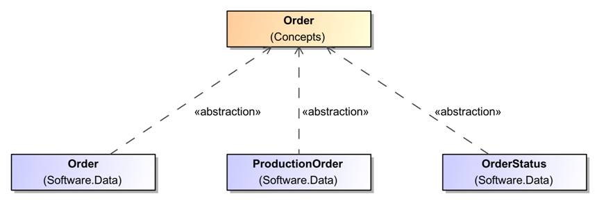
Figure 9. Defining abstraction relationships from software data structures to business concepts
Also, we may enrich our business process models by adding aspects of data objects, their types and even states in which they are expected to be while performing tasks.

Figure 10. A business process with details of data flow: data objects with names, types, and states
Employing Traceability: Navigation, Coverage, Impact Analysis
Once the relationships between software and business models are established, No Magic’s MagicDraw/Cameo Suite modeling environment empowers the analyst to use various tools for model analysis:
-
Find usages or dependencies of a selected model element
-
Explore related elements of a business process task or software system before changing it - in order to estimate the impact
-
Publish reports presenting multiple views with different levels of detail
Thus, an integrated enterprise architecture model connecting business and software systems is shown to be a valuable asset for business and system analysis.
While the produced models are clearly valuable, the modeling itself is also valuable as a means of improving the dialog between business and software teams…so that the relevant questions are asked and the gaps are recognized.
Adopting an Integrated Business and Software Modeling Solution in Your Organization
In the case study, such as the one provided in this article, integrating business and software architecture might seem natural and easy. But in a real life there are many challenges that need to be solved in order to keep business and software architectures consistent and in sync. Successful modeling requires modeling skills, discipline, and an appropriate modeling environment supporting productive modeling and model-based analysis.
No Magic is well known as the developer of MagicDraw and the Cameo Suite modeling platform. This platform enables integrated business and software modeling, provides collaboration and publishing capabilities, and a flexible model validation engine. The No Magic solution can be easily tailored to the needs of the enterprise based on custom validation rule suites, and other features.
In order to use this platform effectively, the organization needs a modeling solution, which combines modeling language(s), and modeling methodology customized to an organization. No Magic provides value-added professional services to help organizations succeed in implementing, deploying and leveraging an effective modeling solution. Offerings include BPMN (and UML if required) training and consulting with the focus on solving business modeling challenges.
In addition, No Magic’s solution customization services are ideal for organizations wishing to tailor MagicDraw with the Cameo Business Modeler Plugin for maximum productivity, e.g., defining a custom suite of validation rules to check model correctness / completeness based on custom modeling guidelines, implementing modeling facilitation plug-ins, or preparing custom report templates.
MagicDraw with the Cameo Business Modeler Plugin provides organizations with the power of business and software modeling based on UML and BPMN standards while relating business concepts and processes to software systems, use cases, and data structures. Such model integration bridges the gap between business and software architectures and improves communication between business analysts and software engineers.
The No Magic professional services team is ready to assist your enterprise in building and deploying a highly effective and consistent modeling solution tailored to your needs, one which integrates both business and software architectures.
Additional Resources
Powerful Business Modeling with No Magic’s Cameo Business Modeler @ Modern Analyst – a previous article from No Magic, which discusses the same case study, yet, focuses on Business Architecture without a connection to Software Architecture
http://www.nomagic.com – for the No Magic homepage where users can find more information on MagicDraw and the Cameo Suite
http://www.nomagic.com/products/cameo-business-modeler.html – specific No Magic webpages for the Cameo Business Modeler solution
http://www.bpmn.org – resource for more information related to Business Process Model and Notation (BPMN) specification
To learn more about bridging the gap between business and software architectures, attend the Third Annual No Magic World Conference February 17-20, 2013 in Dallas. The No Magic conference offers a solid BA track and keynotes from John Zachman, Kathleen Barret and Dr. Richard Soley among others.
For more information and to register go to: http://www.umlconference2013.com/
Authors: Dr. Darius Silingas & Edita Mileviciene, No Magic
Darius Silingas is the Head of the Solutions Group at No Magic Europe. He helps organizations adopt the MagicDraw / Cameo modeling platform for efficient software and business modeling. Darius has delivered over 200 training and consulting sessions in 20 countries, spoken at numerous conferences, and written multiple articles on software and business modeling. Darius holds a Ph.D. in Computer Science and is an OMG Certified UML Professional and Expert in BPM. In addition to his work in the industry, Darius is a part-time Associate Professor in Vytautas Magnus University, and a visiting lecturer in the BPM program at ISM Executive School. Darius can be reached by e-mail at [email protected].
Edita Mileviciene is a Product Manager for Cameo Business Modeler, a plug-in to the MagicDraw modeling platform enabling BPMN 2.0 modeling capabilities. Edita has been working on the MagicDraw R&D team since 2002 in various roles: QA engineer, analyst, and product manager. Edita is also an experienced UML and BPMN consultant, and regularly conducts online and onsite trainings for MagicDraw customers worldwide. She holds a Master’s degree in Computer Science from Kaunas University of Technology and is an OMG Certified UML Professional and Expert in BPM.